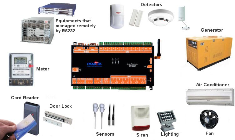

Functions
Security & Card Access
|
Card numbers are stored inside the telemetry device. Those informations can updated directly on the telemetry by embedded web server, or through the remote server.
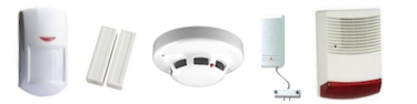
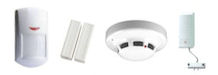
When device is in ARM mode and entrance is occurred without accepted card reading, door magnetic contact(s) or motion detector(s) inputs trigger system to ALARM mode. By Alarm mode, siren output is activated, event log is recorded and sent to remote server, SMS and Emails are sent if defined. If accepted card is read to the reader or Disarm command arrived |
|
from Remote Server , system sets security mode to DISARM mode, siren output is deactivated, event log is recorded and sent.
If accepted card is read to the reader before entrance to the site, device changes its status to DISARM mode, records related logs and sends SMS', Emails to the related destinations and logs to the Remote Server. Smart Telemetry can also control door latch/lock by one of digital outputs to lock/unlock the door. Smart Telemetry can store 100 card numbers to be accepted, but this number can be increased upon request. One of digital input is designed to mount water leakage probe without needing sensor. Sensor is inside the device. Fire/Smoke Alarm sensors can be installed to one of digital inputs. |
 Smart Telemetry supports proximity 125kHz card reader (standard). 13.56Mhz Mifare reader can also be used upon request. Reader is installed during installation as a module inside the telemetry device. The antenna of the reader is mounted by a cable to the smart telemetry device.
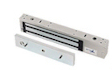
Meter Reading
|
Meter can be read instantly by embedded web server command or by Remote Server command. There are two types of reading. |
One of them is Readout which includes obis codes defined by protocol and meter manufacturer. This type readings can be executed instantly. The other one is about obis codes which are predefined by user, like AMR. This type is more information focused, can read meter instantly and also with a certain time. User can define time to read meter automatically like every day at 08:00 or every month last day at 23:59 etc. Time set can be every day, every week, every month n. day xx:xx time. After meter reading at certain time, device stores information inside the memory. This information can be obtained by embedded web server, or Remote Server. |
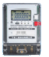 Smart Telemetry, has one RS-485 port for meter reading with EN 62056 international meter reading protocol. Device can read locally connected electricity, natural gas, water meters which support EN62056 protocol within 1200 m. By default device reads one meter through meter port, but firmware can be updated to read up to 32 meters through one port. In that case, all meters serial numbers should be known and stored in the device.
Temperature, Humidity Control and Other Sensors
|
User can define functions about sensor measurements limits. When sensor measurement exceeds the limit, function value is changed, related digital output and/or PWM motor driving is executed. Event logs are recorded, SMS and Emails are sent. |
Sensor Functions Example |

 Smart Telemetry ST1206 has two temperature sensor inputs, one humidity sensor inside, two analog inputs, while STL1206 has six sensors inputs which can be temperature, humidity, dust, air quality, analog, mains voltage, pressure difference sensors.
 I/O Kontrol
Digital Inputs Digital inputs are used for sensors which have dry contact outputs.
Analog InputsSmartek Telemetry ST1206 has two analog inputs, STL1206 has 4 analog inputs(any sensor input number 3-6). Analog inputs are designed to convert analog levels like fuel tank, water tank level sensors.
|
Digital OutputsDigital outputs are 220V AC 4A capable relay outputs which have both NO and NC.
Pulse Width Modulation (PWM) Output
|
 When input is changed (from open contact to closed contact or vice versa) event log is recorded, SMS' and Emails sent, log sent to Remote Server so that any changes are observed by Remote Server. Input functions are calculated instantly, if it is related to any output, they are also updated.
 Analog inputs calculate digital converted value of voltage input, between min and max voltage levels(those voltages are also connected on the connectors). Analog value is converted % ratio of min and max values. Depending on analog or sensor functions, outputs can be activated automatically, logs, SMS', Emails are sent.
 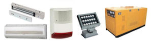 If the load is higher than relay capacity, additional relay or switching devices can be used. Digital outputs are controlled automatically by input, sensor, time functions, and force (manual) change is also available by embedded web server or Remote Server.
Transparent Serial Ports
|
|
Telemetry connects to remote virtual port with Remote Server (client) command. And close connection as well. |
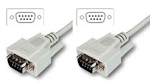 Smart Telemetry, 2 has two (RS-232) serial ports. Those ports can be connected to any two equipment which have RS-232 ports to communicate. Any remote client can connect to those equipments by remote client's virtual serial port through Remote Server. This bridge feature makes client to communicate with equipments with RS-232 remotely. Telemetry's serial port configuration (baud rate (300-115.200), data bits (7/8 bit), parity bits (odd/even) can be set remotely depending on connected equipment's configuration.
Camera Snapshot Control
 In case security alarm status, telemetry sends snapshot order to IP camera twice at the periods of 2s., 10s., 60s., 5min. sequentially.
|
If remote server is defined, telemetry sends all digital Input/Output and Sensor measurements periodically to the server without waiting status changes. |
In case Ethernet connection is not available, Telemetry sends logs through GPRS connection. All settings, functions and firmware can be updated by embedded web server or through Remote Server, real time observation of Inputs, Outputs, Sensor measurements can be done as well. Flexible configuration allows system to send 4 Emails and 4 SMSs for each I/O changes, sensor function status changes (sensor measurement excess limit value which is defined by user in functions) independently. |
 Remotely access to Smartek Telemety is achieved by TCP/IP
Reset and F Buttons
Reset button is located at right side of device to reset device. If F button is pressed at least 20 seconds, factory settings are loaded.
Light and Buzzer Notification
Buzzer inside the Smart Telemetry notify different type of notifications including alarms. One of three leds is about GPRS connectivity. Other 2 of them is about different status notifications.
Real Time Clock
Smart Telemetry has a real time clock. It is powered by special battery inside the device, so it is not affected by mains cutt. Device updates its real time at the beginning of start-up and also periodically from NTP server defined by settings.
Event Logs
Smart Telemetry keeps 1.000 I/O, Temperature, Analog, (and other Sensors) measurements events in its non volatile memory. Card reader transactions log memory keeps 250 logs. Those log lengths can be increased upon request. New logger function has been added to the system. Logger records all sensor measurements periodically without waiting status change of functions.
Log records can be downloaded from the device by embedded web server or remote server. Logs can be deleted on the same way.
Functions and Card Definitions
Accepted rfid card numbers, system settings and functions definitions are kept in device non volatile memory. Those definitions can be download, upload and updated by embedded web server or remote server. Mains cutt does not affect those informations.
Language Support
Embedded Web Server of Smart Telemetry is in English and Turkish. New languages can be added to firmware upon request.
Physical Connections
* If serial numbers of meters are known, one port can read up to 32 meters. Electrical Data
* No GPRS connection, on 12V DC power supply
Dimension Width x Hight x Depth : 215 x 105 x 40 mm (without antenna) |
Temperature Measurement
* Between -10 +85 °C
Analog Measurement
Card Reader
* Affected by magnetic noise of environment
Transparent Serial Ports
|